self-construction |
|

|

|
the first steps
In
1993 to make long-exposure astrophotography, I started to build a
star tracker using parts of household electrical appliances. The idea
came to me after removing the rotisserie motor from an old kitchen
that had a rotation period of 30 seconds.
To reduce the speed of rotation I chose a transmission with pulleys. A first pulley I retrieved from a polishing machine, the other two I had to build them to the lathe for to have the correct size in order to ensure the rotation period wanted. The material had to be lightweight, but strong. I chose the bakelite and the friction between the pulleys was secured by a rubber coating.
For the final "calibration" was enough to adjust the diameter of the motor pulley with tape, a craft system (such as the whole project) but functional.
The camera was mounted on a small Manfrotto head attached to the large pulley and fixed, below, to the ball bearings recovered from the hub of the drum of a washing machine.
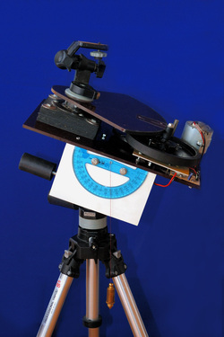
The Polar Alignment was done by compass and protractor with plumb line. Looking at it now, I wonder how it would work...
Unique (so to speak) flaw was the dipendence to the mains 220Vca.
His first release was in August 1993 at the refuge Lagazuoi to 2752m near the Falzarego in the province of Belluno (Italy). Carry the all equipment (camera, lenses, binoculars, tripod, star tracker... and 100m of extension cable!) was not very easy, but was secured by two brave and irreplaceable friends sherpa: Damiano and Simone.
Despite the "summer" temperature of -1 °C and the constant presence of the Murphy's law, was pleasant to observe the meteor shower: while I was photographing the one hand, meteors and bolides fell on the other ...
Back home, I watched with great satisfaction the slides developed, no trace of meteors, but the stars were punctiform.
To reduce the speed of rotation I chose a transmission with pulleys. A first pulley I retrieved from a polishing machine, the other two I had to build them to the lathe for to have the correct size in order to ensure the rotation period wanted. The material had to be lightweight, but strong. I chose the bakelite and the friction between the pulleys was secured by a rubber coating.
For the final "calibration" was enough to adjust the diameter of the motor pulley with tape, a craft system (such as the whole project) but functional.
The camera was mounted on a small Manfrotto head attached to the large pulley and fixed, below, to the ball bearings recovered from the hub of the drum of a washing machine.
The Polar Alignment was done by compass and protractor with plumb line. Looking at it now, I wonder how it would work...
Unique (so to speak) flaw was the dipendence to the mains 220Vca.
His first release was in August 1993 at the refuge Lagazuoi to 2752m near the Falzarego in the province of Belluno (Italy). Carry the all equipment (camera, lenses, binoculars, tripod, star tracker... and 100m of extension cable!) was not very easy, but was secured by two brave and irreplaceable friends sherpa: Damiano and Simone.
Despite the "summer" temperature of -1 °C and the constant presence of the Murphy's law, was pleasant to observe the meteor shower: while I was photographing the one hand, meteors and bolides fell on the other ...
Back home, I watched with great satisfaction the slides developed, no trace of meteors, but the stars were punctiform.

Milky Way in the Sagittarius
Nikon AF 24mm f2.8 |
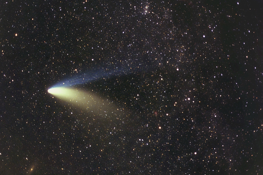
Comet Hale Bopp on March 27, 1997
Nikon AF Micro 60mm f2.8 |
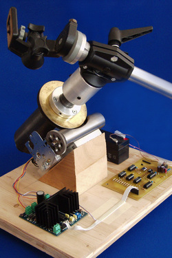
After time, I decided to replace the rotisserie motor with a 12Vcc motor taken from an old projector (shown in photo) so as not to be bound to the main 220Vca, but mainly for the carriage of the extension cable!
The calibration of the speed of rotation was effected by a small electronic circuit. The engine used had, however, a large current consumption that limited the battery life.
the evolution
In
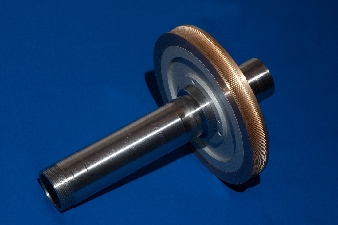
2003 I purchased a bronze gear Z=180 D116 and a worm steel by
OFFICINE MARCON. Then I built another star tracker, this time
driven by a stepper motor controlled by an electronic circuit with
quartz crystal oscillator. The body of the mount has been realized
with a steel tube of 70mm diameter, machined to create inside the
seat of the ball bearings. Even the central axis has been realized
with a steel tube; the inner diameter of 26mm allow the installation
of a small polar scope to facilitate alignment.
The aluminum tube which supported the camera is a MANFROTTO photographic accessory and to balance the weight of the camera I used an adjustable counterweight.
The power board that drives the stepper motor is a kit of New Electronics LX1420, while I built the control circuit that is constituted by a quartz oscillator and a frequency divider. A push-button which acts on a frequency switch allows to vary the speed of tracking.
Aesthetically it was not very nice, but it worked properly. However, it was an instructive work.
the game get harder
After
several projects designed to make improve the
previous star tracker, interspersed with long periods of inactivity,
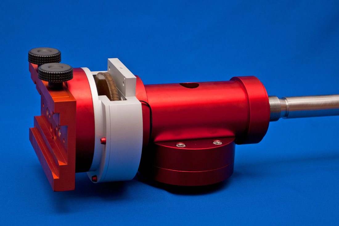
in 2011 I have begun construction of an
equatorial mount "recycling" the wheel and the worm
of star tracker previously constructed that will be used for the DEC
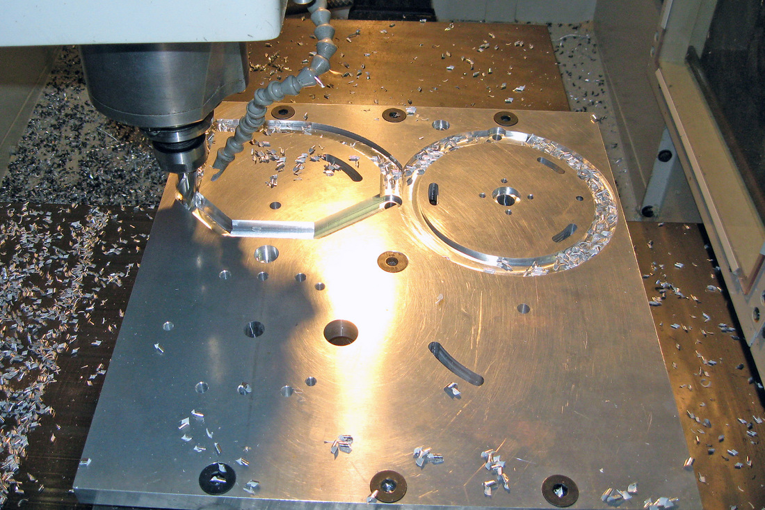
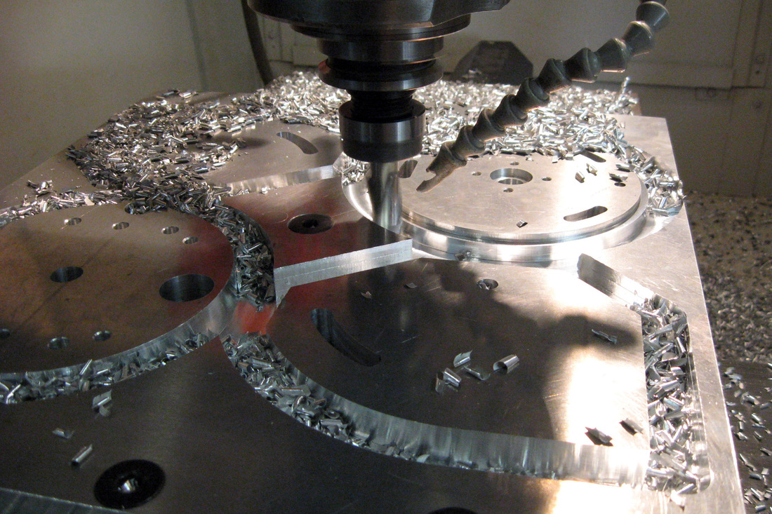
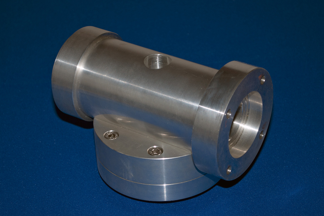
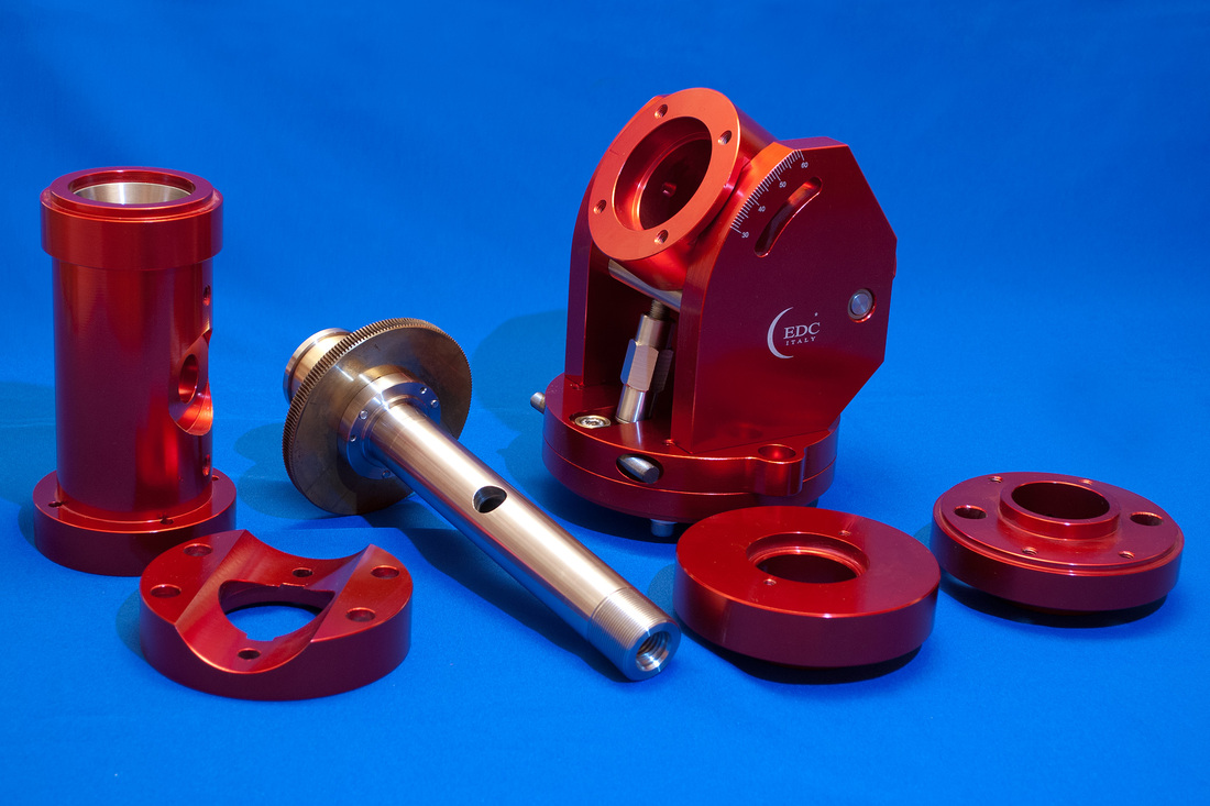
axis. The mount is in aluminum anticorodal 6082 worked with CNC
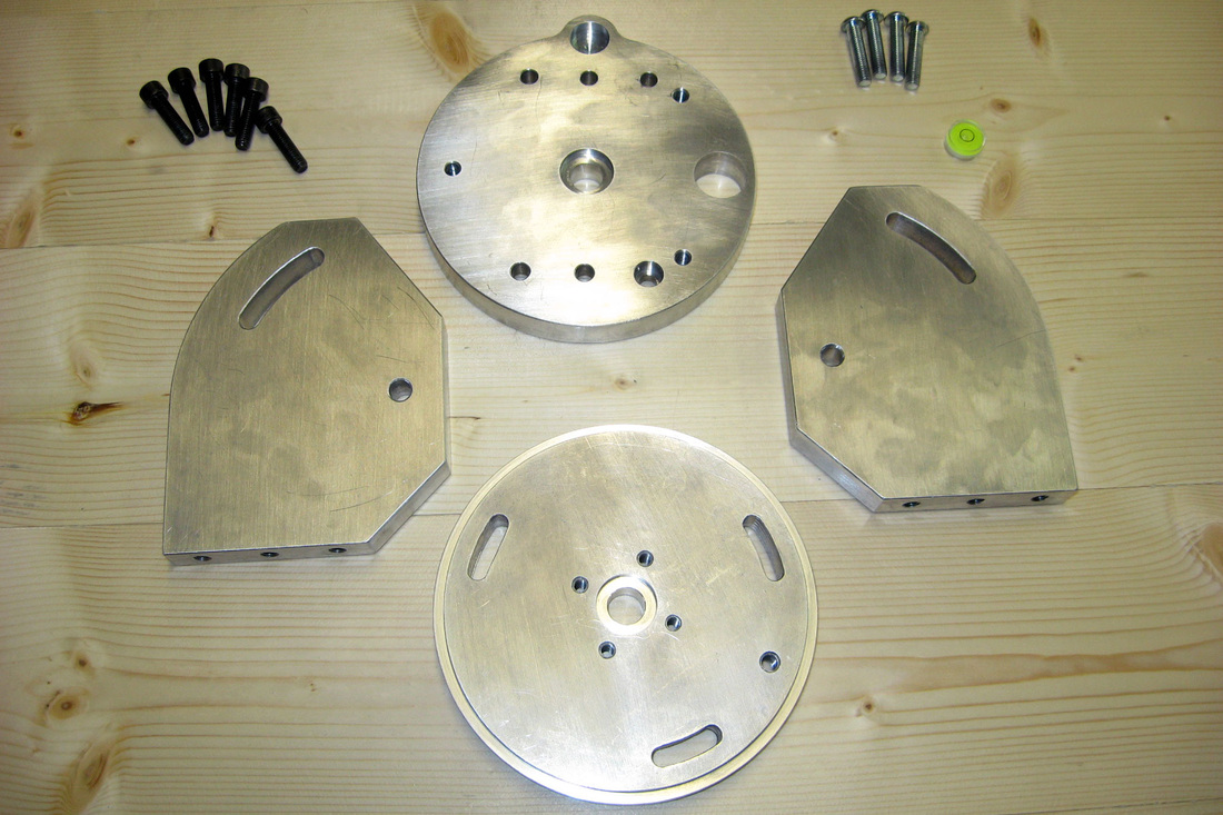
machines. The base is formed by a plate of 20mm thick, in which has
been inserted even a small level, while for the main bodies of the
axes I used a 110mm diameter bar. In the project I had the
indispensable help of two excellent engineers, Giuliano and Mario.
Without their cooperation, the project would have failed.
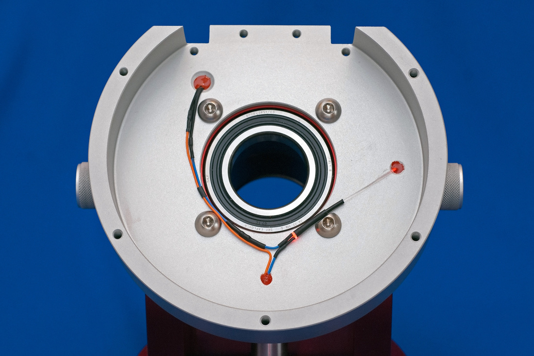
Each of the two axes, made of stainless steel, is kept in place by a pair of bearings FAG:
Click here to see the project.
Each of the two axes, made of stainless steel, is kept in place by a pair of bearings FAG:
- The
axis AR uses a ball bearing 40 68 15 and one tapered roller 40 68 19
- The
axis DEC uses a ball bearing 35 62 14 and one tapered roller 35 62
18
Click here to see the project.
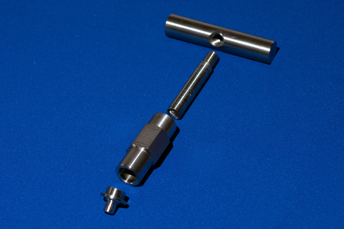
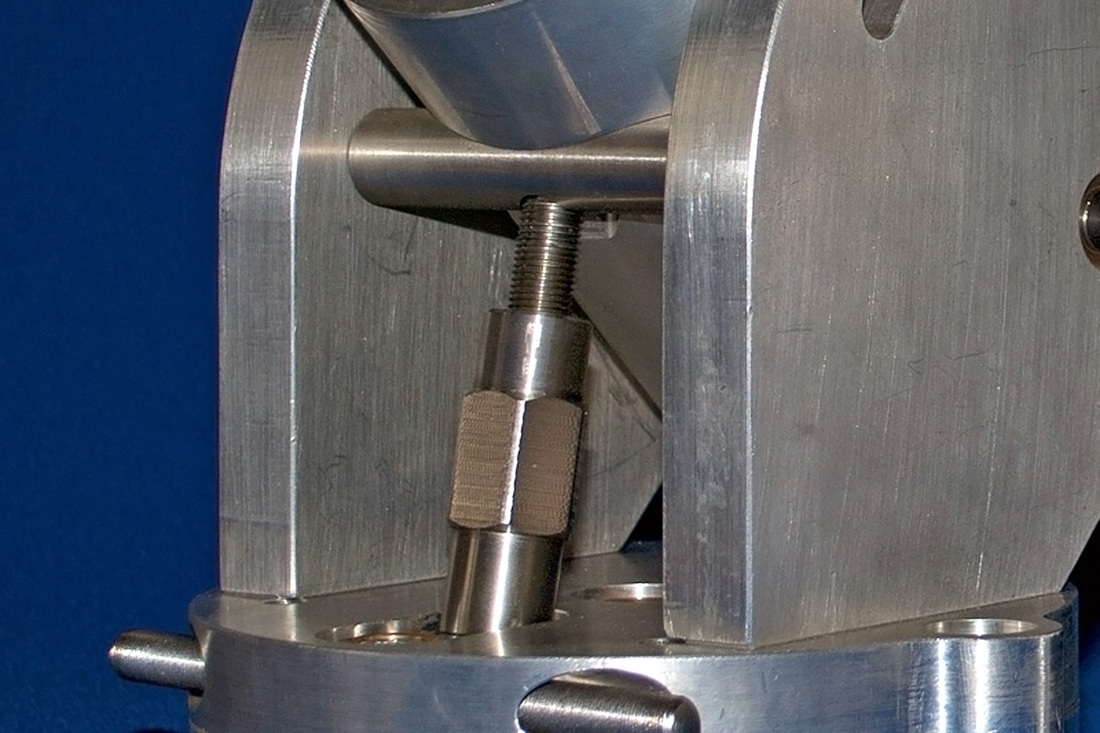
The
mechanism of latitude adjusting was constructed of stainless steel.
It is a bar of 12mm pitch screwed end to a second bar, perpendicular
to the first, in turn inserted into the main body of the frame where
it had been previously realized the hole. In this way has been made
the joint. The other end of the threaded rod is screwed onto a steel
cylinder specially milled to have a hexagonal cross-section.
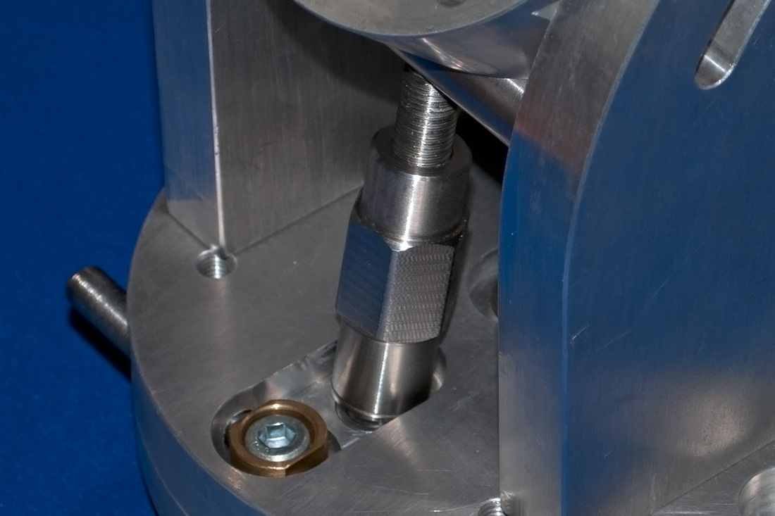
The latter is anchored to the base of the frame by means of a spherical bearing.
I like this solution because it allows you to redirect the weight directly on the mount's based.
The latter is anchored to the base of the frame by means of a spherical bearing.
I like this solution because it allows you to redirect the weight directly on the mount's based.
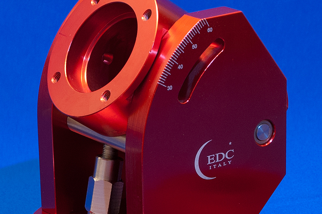
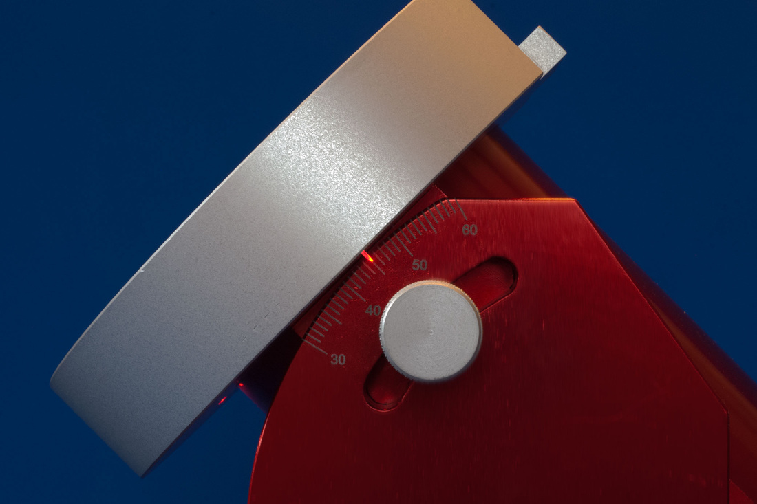
The
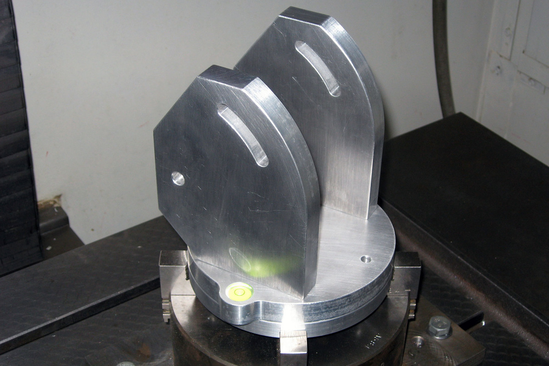
aluminum parts have been anodized in color red, with the exception of
the two discs which cover the crown gear that have been anodized in color aluminum. On the sides of the plates I have engraved with the laser the
scale of latitude. In the throes of enthusiasm I added the initials
of my name. I confess that these were not necessary, but considering that the piece was already in the incision machine I could not resist...

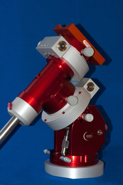
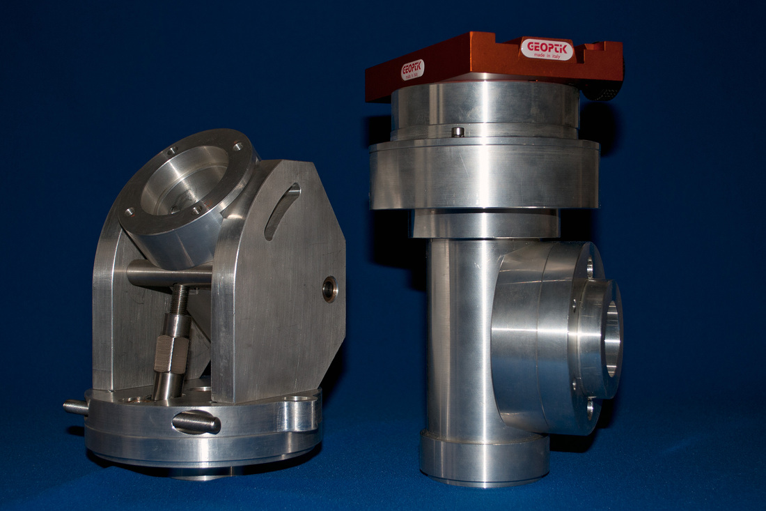
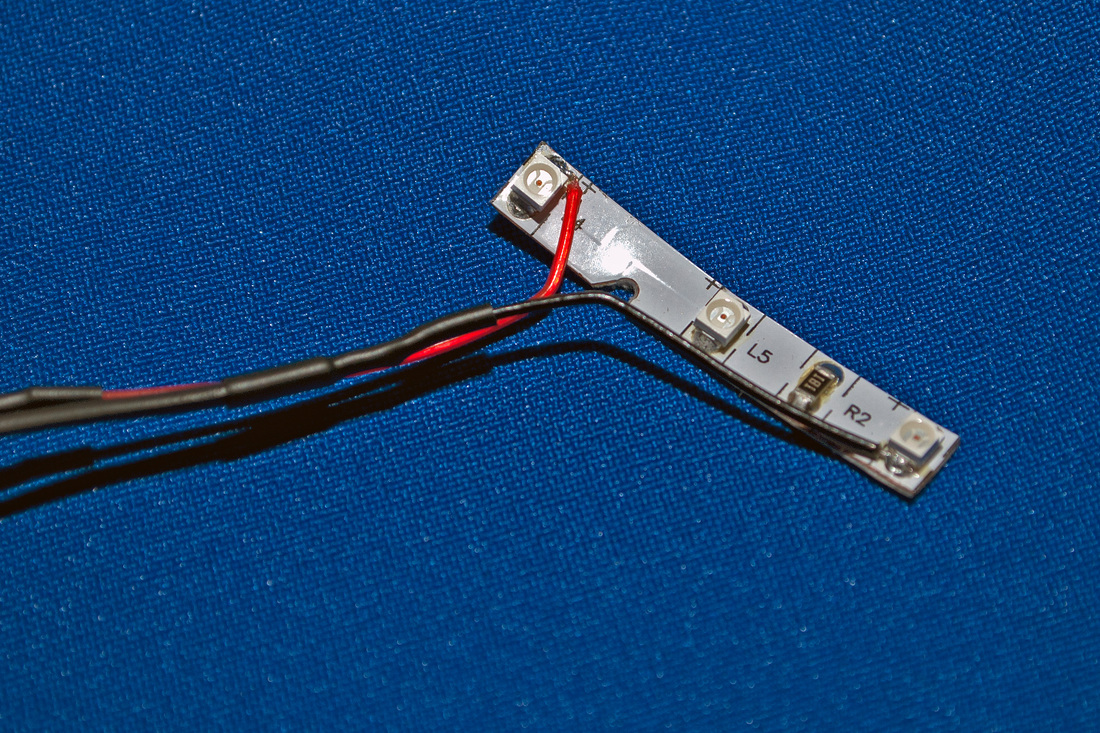
The polar scope reticle illumination is guaranteed by a strip of 3 smd led. This is fixed on the edge of the side hole of the DEC axis. The power cable goes out near of the point where the DEC engine will be fixed. The variable voltage power supply, that goes from 5V to 12V, allows you to adjust the brightness.
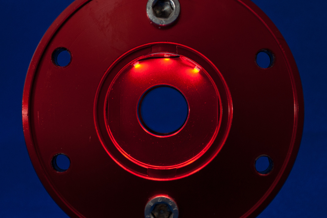
The AR axis is made of stainless steel. To it is fixed the gear Z=300 D153. In the mount I plugged a variable brightness red LED to illuminate the latitude screw. The index of the latitude graduated scale has been realized with an optical fiber suitably shaped and illuminated by a variable brightness red LED. These two options make easier the alignment of the mount when it is dark.
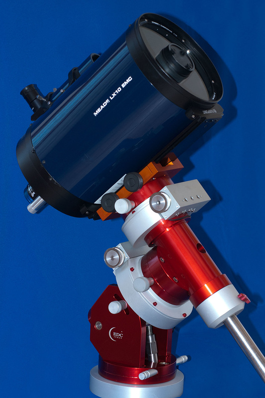
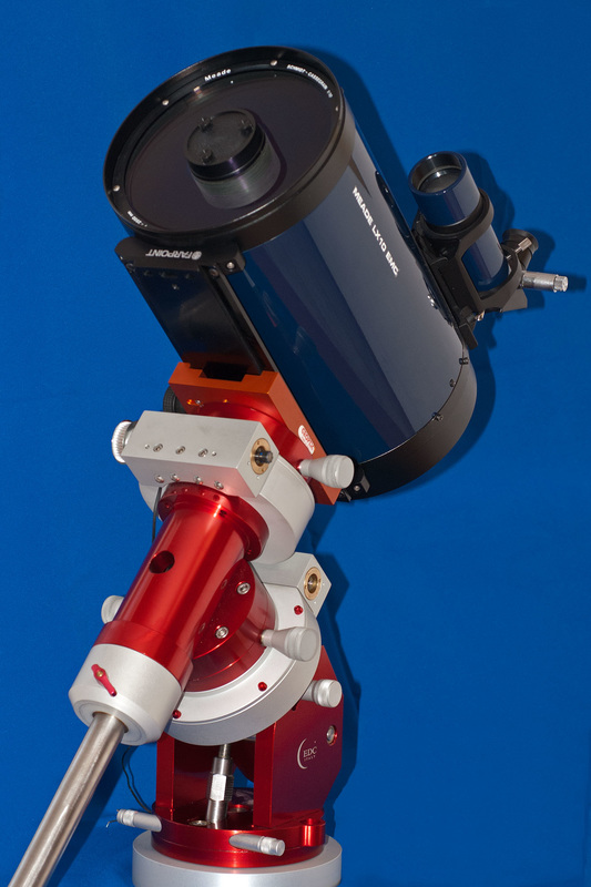
The mount is almost completed, the next step is to install the two stepper motors and encoders on the worms. In the following pictures the mount support a Schmidt-Cassegrain 8 inch Meade.